
No electromagnetic torque is produced and the motor stays still.Īt t = 0.2 s, the torque reference jumps to 600 N.m. The initial torque reference is set to 0 N.m and the armature current is null. The motor is coupled to a linear load, which means that the mechanical torque of the load is proportional to the speed.

A second scope allows you to visualize the converter average output voltages and output currents. The current and torque references are also shown. You can observe the motor armature voltage and current, the converter firing angles, the electromagnetic torque and the motor speed on the scope.
#Three phase rectifier matlab simulink series
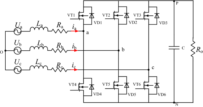
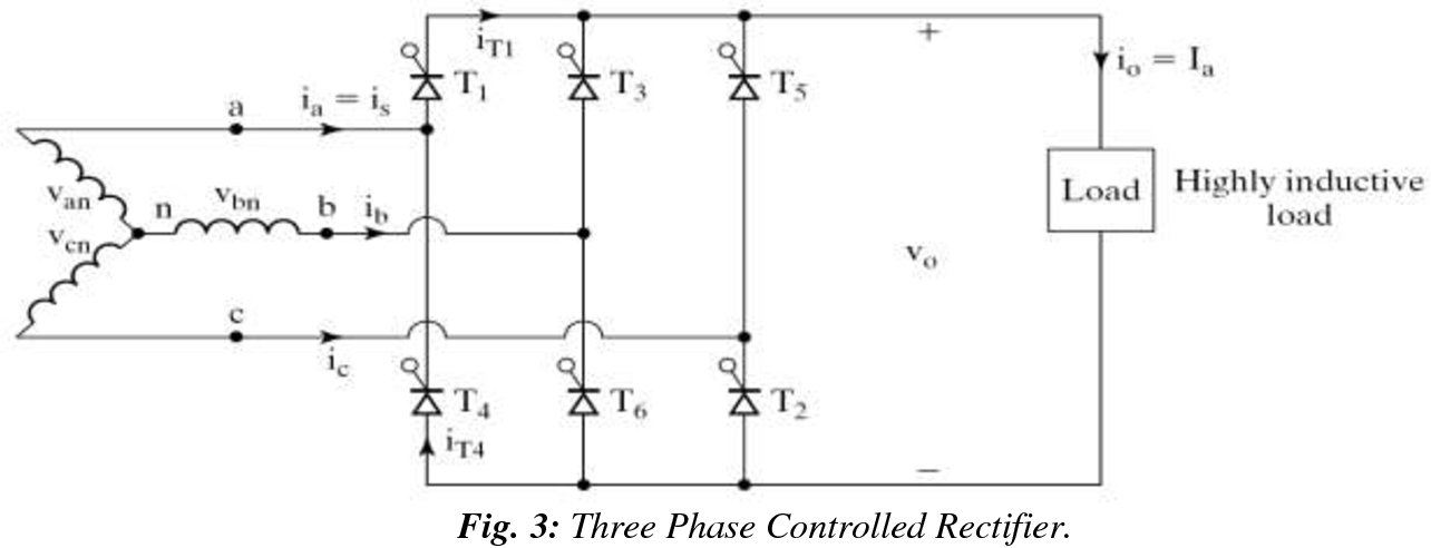
No smoothing inductance is placed in series with the armature circuit, the armature current oscillations being quite small due to the three-phase voltage source. The circulating current produced by the instantaneous voltage difference at the terminal of both converters is limited by 5 mH inductors connected between these terminals. One converter is working in rectifier mode while the other is in inverter mode. This produces opposite average voltages at the converter dc output terminals and thus identical average voltages at the DC motor armature, the converters being connected in anti-parallel. This generates the rectifier output voltages needed to obtain the desired armature current and thus the desired electromagnetic torque.īoth converters operate simultaneously and the two firing angles are controlled so that their sum gives 180 degrees. The current regulator controls the armature current by computing the appropriate thyristor firing angles. Since we are here in torque regulation mode, the speed regulator is disabled and only the current regulator is used. The first regulator is a speed regulator, followed by a current regulator. The regulators control the firing angles of both converter thyristors. The converters are fed by a 380 V AC 50 Hz voltage source.

This allows bidirectional current flow through the DC motor armature circuit and thus four-quadrant operation. The armature voltage is provided by two three-phase anti-parallel connected converters controlled by two PI regulators. The 200 HP DC motor is separately excited with a constant 310 V DC field voltage source. It models a four-quadrant three-phase rectifier (dual-converter topology) drive for a 200 HP DC motor. This circuit uses the DC4 block of Specialized Power Systems.


 0 kommentar(er)
